
一、 Types of joint bearings and tolerance zones for shafts and holes:
1. According to the characteristics of the fit between the inner ring of the bearing and the shaft, the limit deviation of the shaft neck diameter is selected in the base hole fitting.
a) Interference fit: p6, n6, m6, k6
b) Transition coordination: h6, h7, g6
2. According to the characteristics of the fit between the outer ring of the bearing and the housing hole, the limit deviation of the housing hole diameter is selected in the base shaft system fit.
a) Interference fit: N7, M7, K7, J7
b) Transition coordination: H6, H7, H11
二、The basic principles for selecting joint bearings:
1. Based on the type, size, tolerance, clearance, and working conditions of the bearing, as well as the magnitude, direction, and nature of the load acting on the bearing, the materials of the shaft and housing holes, and the ease of assembly and disassembly, the selection of the fit between the bearing and the shaft and housing holes is made.
2. In order to prevent wear and relative rotation of the sleeve on the mating surface between the shaft and the housing hole when the bearing is working under load, the swing sleeve of the bearing should adopt interference fit.
3. To prevent sliding or crawling between the inner ring and the shaft, interference fit should be preferred between the inner ring and the shaft; If clearance fit is chosen for ease of assembly and disassembly or due to the use of floating supports, the surface of the shaft neck should be hardened.
4. When selecting interference fit, the influence of interference fit on radial clearance should be considered. For situations where a larger interference fit is necessary, bearings with original clearance greater than the basic group clearance value should be selected.
5. The fit between bearings, shafts, and housing holes shall comply with the provisions of Table 1 and Table 2.
Table 1 Tolerance Zones of Bearing and Shaft Fit Shaft
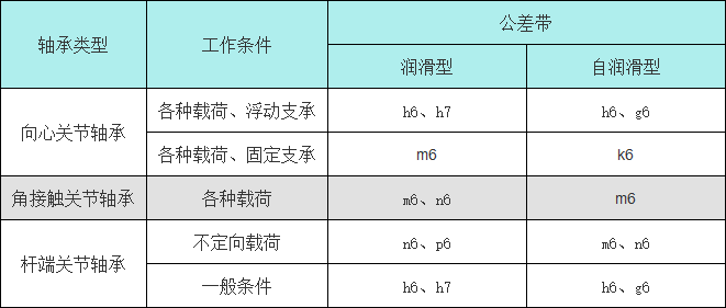
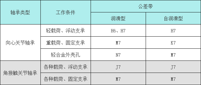
Table 2 Tolerance zones for the mating holes of bearings and housing holes
三、Surface roughness and positional tolerances of the mating surface and carbonyl surface
1. Surface roughness
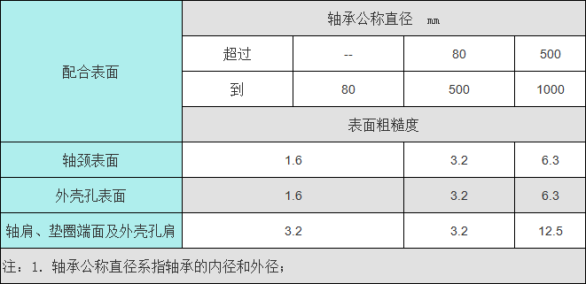
The surface roughness of the mating surface and end face of the journal and housing hole with the bearing shall comply with the provisions of Table 3
Table 3 Surface roughness unit: micrometer
2. Shape tolerance
The shape tolerance and dimensional tolerance of the journal and housing hole surfaces should follow the principle of tolerance.
四、Installation requirements:
1. To prevent interference between the shoulder fillet and the bearing chamfer, ensure good contact between the bearing end face and the shoulder and the shoulder, and ensure reliable positioning of the bearing, the one-way fillet radius of the shoulder and the housing hole shoulder should be smaller than the small one-way chamfer of the bearing inner and outer rings, respectively.
2. For bearings with sealing rings, to ensure good sealing performance, the size of the housing hole shoulder should be larger than the outer diameter of the sealing ring assembly.
2. To fully utilize the allowable tilt angle of the joint bearing, the value of the shoulder diameter when installing the joint bearing should be equal to or less than the diameter of the inner ring end face of the bearing (except for wide inner ring radial joint bearings).
2. For radial joint bearings with split and slotted outer rings, we recommend installing them in a direction perpendicular to the direction of the load and the direction of the bearing slot.
五、Lubrication:
1. Self lubricating joint bearings do not require lubrication, while PTFE materials, sintered bronze composite materials, polyetherimine engineering plastics, and other materials have self-lubricating properties.
2. For joint bearings with sliding contact surfaces made of steel/steel, we recommend using a molybdenum disulfide lithium based grease, which is lubricated by adding lubricant through the joint bearing's oil nozzle or lubrication groove, and outside the hole.